Valve material and connection
The valve is a control component in the fluid delivery system and has functions such as cut-off, regulation, diversion, prevention of backflow, regulation, shunting or overflow relief. Valves for fluid control systems range from the simplest shut-off valves to the extremely complex self-control systems available in a wide variety of sizes and sizes. Valves can be used to control the flow of various types of fluids such as air, water, steam, various corrosive media, mud, oil, liquid metals, and radioactive media. The connection between the valve and the pipe is an important parameter. According to this classification:
1. Threaded connection: The valve body has internal or external thread and is threadedly connected to the pipe.
2. Flange connection: The valve body is flanged and connected to the pipe flange.
3. Welding connection: The valve body has a welding groove and is welded to the pipe.
4. Clamp connection: The valve body has a clamping mouth and is connected with the pipe clamp.
5. Card sleeve connection: Connect with the pipe with a ferrule.
6. Clip connection: The connection form in which the valve and the two pipes are directly clamped together by bolts.
Valve body material:
1. Metal material: Parts such as valve body are made of metal material. Such as cast iron, carbon steel, alloy steel, copper alloy, aluminum alloy, lead alloy, titanium alloy, Monel alloy.
2. Non-metallic materials: parts such as valve bodies are made of non-metallic materials. Such as plastic, ceramics, enamel, glass steel and so on.
3, metal lining: the shape of the valve body is metal, the main surface of the internal contact with the medium is lining, such as rubber, lining plastic, lining ceramics.

Concerned about surprises
Label: Material of the valve Connection method
Previous: Development and use of butterfly valves Next: What are the types of hardware power tools?
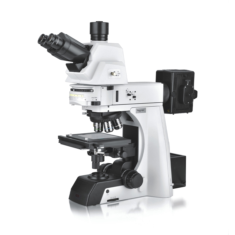
Metallographic Microscope Series
The structure of optical metallographic microscope generally includes magnification system, optical path system and mechanical system, among which the magnification system is the key part. The preparation process of metallographic samples generally includes five steps: sampling, rough grinding, fine grinding, polishing and etching. The interception of samples from metallic materials and parts to be tested is called "sampling". Selection of sampling sites and grinding surfaces must be based on analysis requirements. The size of the sample is not uniform, from the perspective of easy to hold and grinding, the general diameter or side length of 15~20mm, 12~18mm high is suitable. For those too small, irregular shape and the need to protect the edge of the sample, you can adopt Mosaic or mechanical clamping method. For the inlay of metallographic sample, the appropriate size (about φ L5-20mm) of steel tube, plastic tube or paper shell tube is placed on the smooth plastic (or glass) plate, and the sample is placed in the tube to be ground face downwards into the filler, which can be solidified and hardened for a period of time. 3) Chamfering On the premise of not affecting the purpose of observation, the edges and corners on the sample should be ground off to avoid scratching the sandpaper and polishing fabric.
metallurgical analysis,optical microscope for metallurgy,metallurgy microscope
TROJAN (Suzhou) Technology Co., Ltd. , https://www.trojanmaterial.com