Measurement of coaxiality of wind turbine main shaft
Fan main shaft is one of the key components in wind power generation equipment. Our company makes full use of the advantages of special steel smelting, forging, heat treatment and machining, and can produce 0.75~2.5MW wind turbine main shaft products. The steel material is 34CrNiMo6, 42CrMoS4/42CrMo4, and the DIN EN10083-3 standard is implemented.
Coaxiality measurement is a problem encountered in the measurement of various elements of the wind turbine main shaft. The coaxial coordinate detection (CMM) for coaxiality detection and measurement results with high precision and good repeatability is the preferred measurement instrument. However, because the wind turbine main shaft pattern has an objective situation of short reference long distance, can it accurately measure its coaxiality? What issues should I pay attention to during the measurement process? The author has done some analysis on these issues.
1. Briefing
The definition of the coaxial tolerance band in the national standard refers to the area within the cylindrical surface whose diameter tolerance is the value t and which is coaxial with the reference axis. It has the following three control elements: 1 axis and axis. 2 axes and common axis. 3 center and center. Therefore, the main factors affecting the coaxiality are the center position and the axial direction of the measured element and the reference element, especially the axial direction.
Measuring equipment: Hexagon APLLO-IMAGE 25.50.18 coordinate measuring machine (CMM), its maximum allowable error
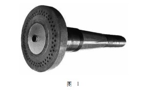
P = 7 10 7L / 1000μm, measurement software: PC - DMIS. The wind turbine main shaft is shown in Figure 1.

Measurement process: After establishing the coordinate system on the end face, according to the pattern, the relevant pattern theory is filled into the automatic feature interface according to the automatic feature needs, and the coaxiality measurement is selected to define the reference. The measurement reference needs to measure 2 circular sections, take two center-constructed spatial lines and use them as reference axes. To select the measurement elements, measure the two-layer circular cross-section structure for coaxiality evaluation.
PC-DMIS software calculation method for coaxiality: twice the maximum 3D distance from the measured axis to the reference axis. For cylindrical geometry elements, the axis is the virtual axis obtained by the software calculation function. The software only calculates the 3D distance from the two endpoints of the virtual axis to the reference axis, with a concentricity that is twice the maximum between the two.
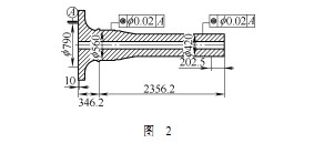
Figure 2 shows the wind turbine main shaft pattern.

The problem arises: The CMM is measured exactly in accordance with the wind turbine main shaft design. The pattern has a clear requirement for the diameter of the reference shaft, but there is no shape requirement. The length of the reference A is 10mm, the distance between the cylinder 1 and the reference is 346 mm, and the distance between the cylinder 2 and the reference is 1200 mm (not shown). There is a short reference distance in the measurement. For the measurement of the coaxiality of the same measurement element with a short reference length, the processing quality of the reference shape and the length of the distance between the measurement elements may cause a linear amplification of the coaxiality measurement result.
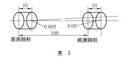
Two cross-section circles are measured on the reference cylinder of the wind turbine main shaft, and the connection is used as the reference axis. Two cross-section circles are also measured on the cylinder to be measured, a straight line is constructed, and the concentricity is calculated. Assume that the distance between the two sections on the reference is 5 mm, and the distance between the first section of the reference and the first section of the cylinder to be measured is 100 mm. If the center position of the second section circle of the reference has a measurement error of 5 μm from the center of the first section circle Then, the reference axis has deviated from the first section of the cylinder to be measured by 5μm (5μmx100÷10). At this time, even if the cylinder to be measured is completely coaxial with the reference, the result will have an error of 100μm (coaxiality tolerance value). For the diameter, 50μm, is the radius), the measurement principle diagram is shown in Figure 3.

2. Solution
By querying the data, it is not recommended to use the measurement software to directly obtain the distance between the reference cylinder (short) and the measured cylinder. Usually, the common axis method, the straightness method and the distance method can be used.
(1) The common axis method measures a circle of a plurality of cross-sections on the measured element and the reference element, and then constructs a 3D line of the center of the circle as a common axis, the diameter of each circle may be inconsistent, and then the reference cylinder is separately calculated. And the coaxiality of the measured cylinder to the common axis, taking its maximum value as the coaxiality of the part. This common axis approximates a simulated mandrel, so this approach approaches the actual assembly process of the workpiece.
(2) Straightness method Measure the circle of multiple cross-sections on the measured element and the reference element, and then select these circles to construct a 3D line, and the coaxiality is approximately twice the straightness. The collected circle is best measured for its full circle. If it is measured on a sector, the deviation calculated by the measurement software may be large.
(3) Finding distance method The coaxiality is twice the maximum distance between the measured element and the axis of the reference element. To calculate the maximum distance between the measured element and the reference element, use the relationship and multiply it by 2. The distance method is calculated by projecting it onto a plane when calculating the maximum distance, so this plane is better than the perpendicularity used as the reference axis. This situation is more suitable for measuring the same pumping degree.
Hardness testers use a differential-depth method. The test consists of placing an on the material, then applying a minor load, which establishes the zero position. After the minor load, a major load is applied and then removed while the minor load is maintained.
Hardness Tester Calibration Calibrating Most Types and Models. Hardness Tester Calibration should be performed on a periodic basis to verify that the accuracy of the instrument is within the manufacturer`s stated tolerances for the grade or model. As a hardness tester repeatedly measures the relative resistance of materials to denting, bending, or scratching, it can become misaligned. hardness tester is a compact device and occupies minimal bench space. A hardness tester commonly constitutes a tester assembly joined to a frame assembly. The tester assembly is made up of a tester enclosure that supports a motor that drives to connect with a load unit and an indentor.
Hardness Tester,Portable Hardness Tester Testing Instrument,Leeb Hardness Tester Laihua Testing Instrument,Brinell Hardness Tester Laihua Testing Instrument
Xi'an Lonn M&E Equipment Co., Ltd. , https://www.smartmeasurer.com