Application of HyperMesh in Strength Calculation of Transfer Case (2)

Figure 3 Finite element model of the rear shell after applying boundary conditions
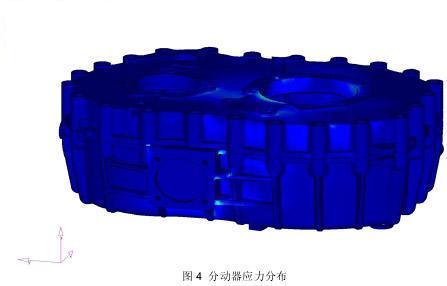
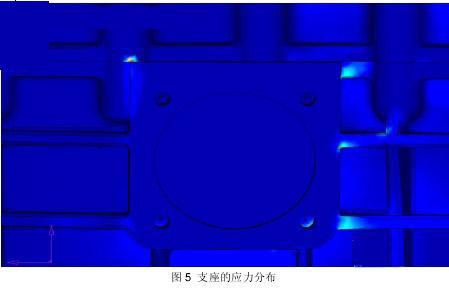
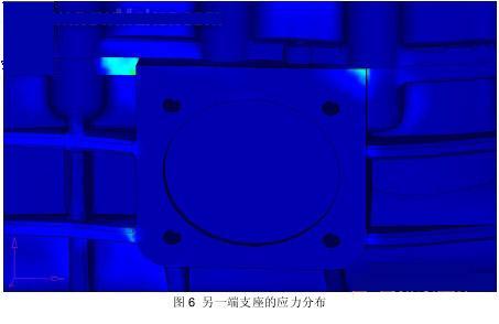
The model is calculated, and Figure 4 shows the calculated stress distribution on the transfer case. It can be seen from Fig. 4 and Fig. 5 that the maximum stress in the model is at the upper left corner of the transfer case and the part connected to the front and rear housings, where the stress exceeds the yield limit of the material, while the rest of the transfer case The stress values ​​are all less than the yield limit. It can be seen from Fig. 6 that the stress value near the upper right corner of the other end support is larger than the stress value of other parts of the support. Figure 5 and Figure 6 show that the sharp angle of the bearing has a great influence on the stress value, while the stress value on the rib around the two ends of the support does not exceed the yield limit, but the stress level of the joint between the rib and the support is higher than that of the support. The stress level in other parts of the seat is high.


3 Conclusion
From the above analysis, the following conclusions can be drawn: the transfer case made of special material basically meets the strength requirement; for the part where the stress value exceeds the yield limit, it is recommended that the designer flatten the sharp corner of the support to reduce the locality. The stress level requirements, while reducing the use of ribs near the support, simplify the transfer structure.
Previous page
Ultraviolet Lamp,Pls Uvc Light,Pls Uvc Bulb,Pls Uvc Tube
Changxing leboom lighting product CO.Ltd. , https://www.leboomuv.com