Factors to be considered in mold design to avoid folding of forgings (figure)
The folding of the aluminum alloy die forgings destroys the continuity of the metal and reduces the bearing capacity of the forging, which is the main waste in the forging production. According to years of production practice and experimental research, the reasons for the folding and the elimination methods are analyzed, and the measures to be taken in the mold design are proposed to reduce the folding and improve the yield of forgings.
First, the folding defects of the die forgings and the causes
During the molding deformation process, the metal always follows the minimum resistance law and flows in the minimum obstruction direction, so that the surface metal flows to the inside of the forging in the local area of ​​the die forging. This flow from the surface to the inside of the forging causes the oxide layer of the skin and lubricant and other impurities. Folding into the inside of the forging together causes folding [1-2] . The reason for this is that the design of the die forging is unreasonable, the radius of the concave fillet (that is, the radius of the convex fillet of the die) is too small, and the change of each section is too large; the wool die, the pre-forging die and the final forging die are improperly matched, and the metal distribution Unreasonable, too much or too little local metal, resulting in uneven deformation during final forging; forgings with complex shapes, directly with a circle
The blank is formed in the final forging die, and the pre-forging die and the wool die are not used; the blank selection is unreasonable, the shape is improper, the pressing amount is too large; the excessive oil is applied or the oil is uneven; the forging edge is too sharp, or the last time After the molding, the repair is not complete.
When the molded part which produces the folding defect is cut and subjected to low-fold examination, it can be found that the surface of the die forging is folded into a forged piece to form an obvious black line, which is called a crease, as shown in FIG. The distance from the surface of the die forging to the end of the crease, that is, the length of the pleat is called the folding depth.

Figure 1 Typical folding of a die forging (low magnification)
Folding has a serious effect on the quality of the die forgings. Firstly, the folding destroys the integrity of the surface of the die forging, so that the load bearing area of ​​the workpiece is greatly reduced. Folding itself is a gap in the part, which causes stress concentration during use and becomes a source of fatigue, which may cause fatigue fracture of the part. Secondly, the creases are mixed with lubricants or other impurities. In the subsequent etching process, the residual liquid of acid and alkali remains in the creases, which may cause corrosion of the parts at the fold. From the internal structure of the die forging, the flow pattern of the metal on the surface of the fold will generate eddy current or flow through, and the more severe the folding, the more the metal flow line will be less smooth.
The generation of folding defects consists of three processes: surface folding, folding formation and folding development. At the initial stage of folding, the trailing ends of the pleats are rounded (see Figure 2). If the deformation is large, the end of the crease can be split or cracked (see Figure 3). Extremely severe folding will break the entire rib shape of the die forging (see Figure 4). Generally, the folding at a certain place is mainly composed of one main pleat. The fold formed by a single pleat is deeper, and the fold formed by the multiple pleats is shallower.
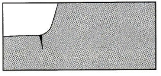
Figure 2 The primary folds and the crease ends are rounded
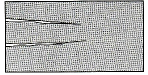
Figure 3 Folding the end of the fold 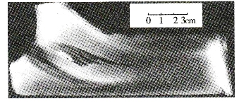
Figure 4 severely folded through the broken tendon
A large number of light alloy die forgings produced on site belong to ordinary open die forging, and there is a certain margin between the forgings and their parts, as well as the die forging slope and large rounded corners. Therefore, although some die forgings have partial folding defects, it is in accordance with the technical requirements of the product as long as the depth of the folding does not exceed the machining allowance, that is, the final folding portion remains on the main body of the part. Therefore, in the field production, the method of cutting is used to determine whether the forging is scrapped. Years of practice have proved that this method of cutting is to identify whether folding defects constitute an effective and convenient inspection method for forging scraps.
Folding can be divided into four types according to its position: rib root folding, rib top folding, corner folding, and edge folding. According to the mechanism it produces, it can be divided into five types: piercing, folding, rewinding, converging and compacting. The causes and influencing factors of folding are various, which can be summarized into three aspects: factors considered from the part drawing to the die forging drawing design process; factors in production process preparation; factors in production specific operations. The factors that should be considered in the mold design process to eliminate the folding of the forging are discussed below.
Second, the necessary shape simplification in the design of die forgings
The shape of the die forging should be as close as possible to the shape of the part, but the necessary shape simplification is necessary in order to facilitate the smooth completion of the die forging and to eliminate the die forging defects such as folding.
Production practice has proved that the main reason for the folding is that after the metal has filled the cavity, due to the presence of too much metal, the underpressure of the forging (referred to as the underpressure) is too large, in order to reduce the underpressure. Even if too much metal is discharged in the form of burrs, it must continue to be deformed by pressure. This is the most prone to folding during excessive outflow of metal, and these folds are concentrated in the fillet where the root of the die is connected to the web.
A die forging having a frame-shaped closing rib is liable to be folded at the inner rib root. It can be seen from Fig. 5a that the eight positions indicated by the arrows are all prone to folding. In order to reduce the folding, the shape is simplified in the design of the die forging, and although the machining allowance is increased, the folding can be greatly reduced. There are only two foldable positions as shown in Fig. 5b. If the shape is further simplified as shown in Fig. 5c, the folding in Fig. 5a can be completely avoided.

Figure 5 Effect of different design schemes on the generation of folds
In Figure 6a, the spacing between the two ribs is less than the rib height b, which is most likely to result in severe folding throughout the arrows. If you can simplify it to Figure 6b, you will eliminate these folds.
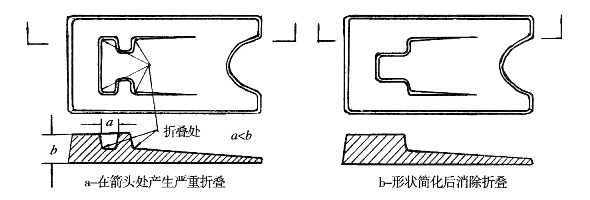
Figure 6 The effect of the necessary shape simplification in the mold design on the folding
It can be seen from the above examples that in the mold design process, the necessary shape simplification measures are taken for different forgings or different parts, which is of great significance for ensuring folding defects during the forging forming process of the die forgings.
Third, the influence of the choice of the parting surface on the folding
In ordinary open die forging, the correctness of the parting surface selection will not only directly affect the smooth completion of the molding, the length of the mold life, the level of production efficiency, but also have an important impact on the quality of the forging. The factors that should be considered when selecting the parting surface are explained below only from the effect of the folding.
Figure 7 shows that the same die forgings, if three different parting faces are selected, will result in different folding: Figure 7a is divided into the middle of the web, and the surface of the rib and the web is only h 2 , so The gold dollar at the rounded corner is very easy to participate in the outflow, and the result is the most likely to cause folding. The parting surface of Fig. 7b is provided on the end surface of the web so that the distance between the rib root and the web surface is H, and the metal of the web makes the round corner R farther than that of Fig. 7a. The surface of the die face, the metal at the corner of the rib, is not easily folded into the outflow as shown in Fig. 7a, but it is still difficult to avoid folding. And as shown in Figure 7c, the parting surface is changed to the top of the rib, so that the molding conditions are changed from the press-in forming of Figures 7a and 7b to the reverse extrusion molding. When the excess metal removal is sequentially flowed in sequence, it is completely avoided. Possible folding in 7b.

Figure 7 Different models have different effects on the folding (P is the same, ↓ indicates the parting surface)
Figure 8 shows the effect of the different parting molds on the face of the I-shaped section. The parting surface of Figure 8a is chosen in the middle, which will tend to fold at the four rounded corners where the ribs and webs are joined, and the metal flow lines on the section will also flow through. In Figure 8b, the parting surface is selected at the top of the rib so that the rounded corners connecting the rib to the web will not fold.

Figure 8 I-shaped section selection of different models to face the impact of folding
As can be seen from the above examples, in order to eliminate the folding, in consideration of other factors in the design of the mold, sufficient consideration should be given to the effect of the splitting on the folding.
Fourth, the choice of the corner radius of the die forging
All corners of the die forging are designed to facilitate rounding of the metal and to minimize the wear of the mold. Each surface of all die forgings is connected by a fillet, a fillet, a horizontal fillet and a horizontal fillet.
Figure 9 shows various fillets for a certain forging. Among them, the inner round corner is generally not easy to fold, and only a single forging may have a rib top covering and folding. It is not easy to produce a rib root fold at the outer round corner (wearing the rib fold). There is generally no folding on the horizontal fillet, only the horizontal fillet at the lower a'-a' of the illustration is at the junction with the rib and the web, as it is located at the turn where the forging geometry changes At the ends of the ribs on both sides, the obstruction of the lateral flow of the web on the sides of the ribs suddenly disappears, and a large amount of lateral flow of the metal occurs, resulting in the forging being not formed. As the deformation continues, the non-formed part is adjacent.
The near web and the metal on the ribs are filled and finally form a fold. The horizontal rounded corners d, e, and f are all equal to 90°, and the angle is generally not easy to fold, but in terms of d, since it is at the corner of the entire forging, the metal on the longitudinal rib and the horizontal rib has vertical and horizontal Flow (see Figure 10). The flow components of these two different directions form a 45° outward force at this corner, and this resultant force will be the main factor leading to the folding. If you increase the radius of this horizontal fillet from the design, you can reduce the risk of folding.
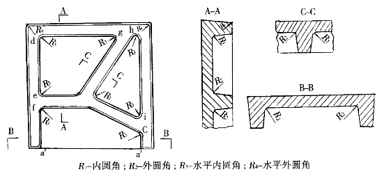
Figure 9 Classification of the general die forgings and the effect of the rounded corners on the folding
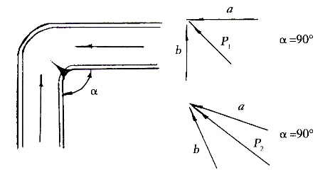
Figure 10: The relationship between the angle-folding procedure and the angle
In the horizontal fillets g, h, i, they are all angles less than 90°, and the metal flow resultant is represented by the following two equations (see Figure 10):
When α = 90°, the resultant force P 1 2 = a 2 + b 2
When α<90°, the resultant force P 2 2 =a 2 +b 2 +2a•b•cosa
When α<90°, the remaining chord values ​​are greater than 0, ∴P 2 >P 1
This shows that when the angle is less than 90°, the metal is more likely to flow out here, which is more likely to be folded, and the folding becomes more serious as the angle is smaller. In particular, as shown in Figure 9, both g and h are located at the end angle of the forging, which is more sensitive to the creation of the fold. For these places, large horizontal fillet radii must be used in mold design to improve metal flow to avoid folding.
The following discussion focuses on the connection of ribs and webs, that is, the effect of the size of the outer fillet on the folding, the effect is divided into two parts:
(1) At the beginning of the first molding (Figure 11)
When the metal is filled into the cavity, if R is too small, the deformed metal does not flow into the cavity close to the rounded corner, and contacts the outer wall of the cavity opposite to the rounded corner along the inertia of the metal flow, and then rushes to the top of the rib, and then from the rib. The top return reverses to the outside of the fillet, resulting in a fold at the fillet. This folding can be avoided if R is chosen properly.
(2) The effect of R size on folding when excess metal is discharged after the metal is filled in the cavity
In ordinary open die forging, the amount of blank is generally 20% to 15% more than the amount of metal required for die forging. After the forging to metal is filled with the model, a part of the excess metal will be from the forging in the form of flash. Upflow to the flash bin, the flow of this metal is by no means ideally flowing as shown in Figure 12a. In fact, these excess metals always follow the minimum resistance law to select their shortcut flow, and Figure 12b is the true flow of metal. These excess metal amounts are present in the form of under-pressure on the web of the forging and in the direction perpendicular to the parting surface. When they flow out, they pass through the rib type and directly rush to the parting surface, if the lubrication is improper or the deformation speed is fast. It will cause the forgings to have irregular flow and folds. This type of rib folding is the main type of folding defects. Figure 1 is a typical photograph of this folding. In order to avoid this folding, the mold should be designed with a large outer radius. In Figure 13, the junction of the same rib and web is assumed to be given a different radius of the fillet, where R 1 & lt; R 2 . When the outer radius of R 1, the excess metal outflow obstruction web frictional surface length of a; when the outer radius is 2, R, which obstruct the outflow of the metal friction surface length b. b is much larger than α because the resistance is proportional to the size of the friction surface, and the resistance generated by R 2 is much larger than that of R 1 . This forces excess metal on the web to flow outwardly from the interior of the metal away from the surface of the forging, even if the surface metal does not participate in the outflow, thereby greatly reducing the penetration.
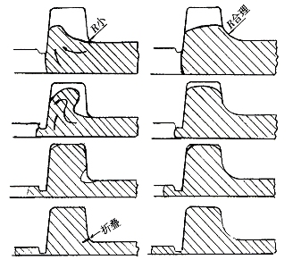
Figure 11 R process of folding a small deformed metal to form a fold
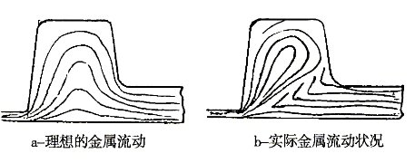
Figure 12 Metal flow on the ribs
On the same die forging, the influence of the rounded corners at different positions on the folding is also different, and the R value selected in the design should also be different. In Fig. 14, R 1 , R 2 , and R 3 are the radii of the outer corners at different positions, respectively. R 1 is the most foldable in terms of its position. The choice of R 1 is related to the rib width B, the rib height H or the web thickness h: from the rib width, R 1 and R 3 are corresponding positions because the rib thickness B 3 at R 3 is much larger than B 2 . The thick ribs pose a great obstacle to the outflow of the metal through the web, so the metal at R 3 is difficult to produce a rib fold, and R 3 can be chosen to be smaller than R 1 . From the height of the ribs, R 1 and R 1-1 are the upper and lower adjacent positions, but at different rib height positions. The rib height at R 1 is H, and the rib height at R 1-1 is H 1 , H 1
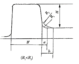
Figure 13 different fillet radii affect the folding 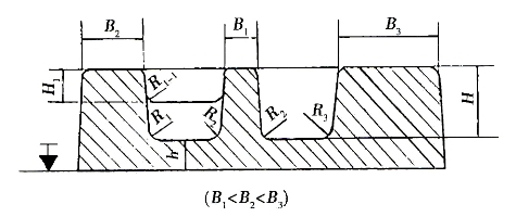
Figure 14 shows the different fillets at different locations.
Fifth, the impact of the size of the die forging on the folding
In the ordinary open die forging, all the geometric shapes leaving the parting surface are formed with a certain inclination angle on the joint surface or the ridge line with the parting surface, which is called the die forging slope. It not only affects the forming of forgings, the wear of the molds and the demolding of the forgings, but also has a certain influence on the folding. But its effect is not as sensitive as the radius of the fillet. The different slopes used for the connection of the rib type to the parting surface and the web shown in Fig. 15 are used. When 3° is used, the length of the contact point between the rib and the web is α; if 7° is used, the length of the connection between the rib and the web is b. b>α, in order to prevent the metal from participating in the outflow at the corner, the 7° obstruction effect is stronger than 3°, so it is not easy to produce folding: so from the avoidance and reduction of folding, the die forging slope should be selected as large as possible. . Usually used in production a large number of 7 °, and some use 5 ° or l0 °.
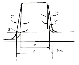
Figure 15 Effect of die forging slope on folding
Sixth, the combination of appropriate shape die forgings to eliminate folding
There are some forgings that are easy to produce folds. According to their specific shapes, they can be placed on the same set of molds by double or multi-type combination according to the ability of the equipment to achieve the purpose of eliminating the folding. The forgings shown in Fig. 16a In the single-die design, the transverse pressure centerline must be placed in the middle of the forging, and the metal on the left side of the pressure centerline will flow outward through the die, so that it is difficult to avoid the transverse ribs at the "R" in the rib root. The long ribs are folded. If it is shown in Figure 16b, the two forgings are combined on the same set of molds to form a new geometric shape, so that the outflow metal flows away from the transverse ribs to the outside, completely avoiding the single-type arrangement of Figure 16a. The ribs are folded. The combined forgings can be cut along the centerline prior to the finished product process.
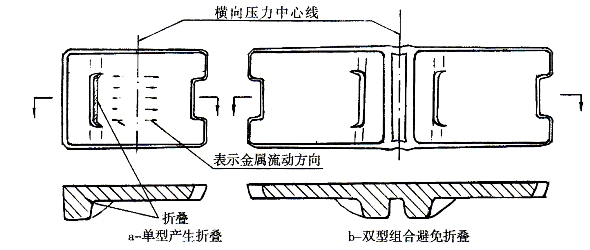
Figure 16 Die forging type groove symmetrical combination design to avoid folding
Seven, the use of wool pressure and pre-pressing mold to eliminate the effect of folding
Some parts with extremely complicated shapes and widely varying cross-sections are not only difficult to select wool, but also difficult to mold, and the deformation is extremely uneven, and folding defects are easily generated. These parts cannot be finished with a set of final die forging, and must be pre-compressed or designed with a wool mold.
The wool mold has only the preliminary contour of the die forging, and the metal is distributed according to the requirements of the die forging. The total metal amount is 10% to 8% more than the final requirement.
The pre-pressing die has the shape of the die forging, but the height of the rib is shorter than the final requirement, the web is thicker, the rounded corner is larger, and the total metal amount is 8% to 5% more than the final forging.
It can be seen from Fig. 17 that from the squeezing-pre-pressing-final pressing, the forgings are gradually filled from the coarse to the fine, so that the flow of the deformed metal becomes smoother and the deformation is more uniform, which can reduce the deformation due to severe deformation. Create a chance to fold.
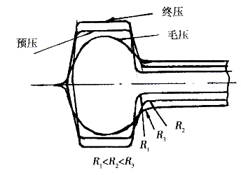
Figure 17 Setting the wool mold, pre-pressing mold, and final pressing mold to avoid folding
Eight, the conclusion
Under the premise of reasonable mold design, process preparation and production operation, the operator's technical level can be fully utilized, and the various processes can be controlled reasonably, which can reduce the folding of the die forging parts or completely avoid folding, thereby reducing the scrap rate and improving the economy. benefit.
Handmade Apron Kitchen Sink,Kitchen Sink,Stainless Handmade Apron Farmhouse,Handmade Apron Farmhouse Kitchen Sink
Guangdong Huayou Hardware Products Co.,Ltd , https://www.gudsink.com