Steering pin processing
  figure 1 |
 figure 2 |
 image 3 |
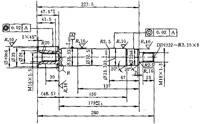
The steering pin parts (Figure 1) have the following characteristics:
- The material is 42CrMoS4V, which is a medium carbon steel and has been tempered. The hardness is 300-350HB and the strength is 1000-1200MPa.
- The dimensional accuracy of the parts is very high, two of which are IT5~IT6 (ie 2-Ø33.333 -0.013 , two places are IT6 (ie Ø32t6 and Ø40n6);
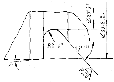
- There is an overpass with a 45° (+15°) bevel;
- The other three mating faces have a coaxiality with the reference A of 0.02.
- Four surfaces with matching requirements, the roughness requirement is Rz10μm (between Ra 1.6~3.2μm).
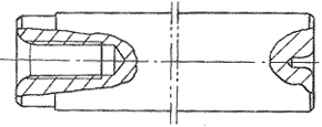
According to the characteristics of the parts and the existing equipment level of our factory, the process route is set for sawing - car end face, center hole - the other end face of the car and the outer circle, drilling, tapping - rough, fine car outer circle - cleaning.
Because the first few processes are simple here, we are focusing on the rough and fine car outer circle. After the first three processes, the workpiece has been processed from a Ø42mm bar to a semi-finished product (Figure 2). This process is processed on the Daewoo Heavy Industries (DAEWOO) CNC car (model PUMA12L-B, spindle motor power 22kW, spindle maximum speed 2500r/min).
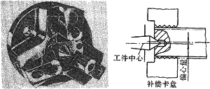
- Step 1: Clean the chuck, the workpiece is loaded with two top-loading workpieces. The structure of the chuck is shown in Figure 3. The main feature is that the center of the chuck has a dead end with a carbide end. Positioning, its three claws are floating, only play the role of clamping, and no longer play the role of automatic centering, which will not cause over-positioning. Before machining the workpiece, it is necessary to correct the machine chuck and the top of the machine to ensure that the top beat is within 0.003mm. In addition, the tip mounted on the tailstock must also be corrected to control its jitter to within 0.01 mm, and the tip itself must have a certain degree of rotation accuracy.
- Step 2: The clamping pressures of the rough outer contour chuck and the tailstock tip are 1.5 MPa and 1.0 MPa, respectively, and remain unchanged until the finishing of the car. Due to the high material hardness of the workpiece, we used the SC4015 (a more wear-resistant grade than the original GC4025) SANDVIK blade with a cutting speed of 160m/min.
- Step 3: The outer contour of the semi-finished car, except for Ø32t6, 2-Ø33.333 -0.013 , Ø40n6, leaving 0.1mm for the refined car balance, the rest of the processing to the drawing requirements.
We chose a relief angle (c 'r = 52 °) larger tool (MVJNR2525M16), the tape 45 ° (+ 15 °) angle overtravel out of the car with the grooves may, without resorting to forming tools, Save on the cost of non-standard tools. We still use the blade of Sandvik brand GC4015, the radius of the corner of the tool tip is R0.4mm, which not only solves the problem of turning vibration, but also solves the problem of surface roughness. - Step 4: The thread is M18×1.5.
- Step 5: Finishing Ø32t6, 2-Ø33.333 -0.013 , Ø40n6 four mating surfaces to the drawing requirements. This step is the focus and difficulty of processing. Therefore, after processing the M18×1.5 thread, the chuck should be loosened before the outer circle of the finished car, and then the workpiece is re-clamped, but the clamping pressure of the chuck is reduced to 0.6 MPa, which is mainly to ensure the coaxiality of the workpiece. The two actions of releasing the chuck and re-pressing the workpiece at low pressure have been written into the program and are completely automated by the machine. The clamping pressure at the top of the tailstock remains unchanged. The finishing tool uses a cermet insert (scheduled), which has the advantage that the life of the tool is significantly improved (up 275% compared to the average tool); the cutting speed is increased by more than 40%; it is cheaper than the carbide insert (referring to the same specification) The size of the workpiece during processing is relatively stable, and it is not necessary to perform tool compensation frequently, saving a lot of auxiliary time. When the same tool is machining four different parts of the same workpiece, we call four tool offsets, each of which controls a size, so that each size can be independently compensated. In addition, in order to make the processing process more stable and reduce the scrap rate, the operator is required to preheat the machine for half an hour before the formal machining of the workpiece, and preheat the finishing tool.
By adopting the above-mentioned series of measures, we successfully produced parts that meet the requirements of the drawings, and controlled the waste within 1%, and the time required to process a part was 4.5 minutes (including the loading and unloading time).
| Manufacturer | Blade model | Blade material | Cutting speed (m/min) | Feed rate (mm/r) | Number of parts processed (piece/blade) | Remarks |
| A | TNMG160408-PF | GC 4015 | 160 | 0.12 | 20 | Cemented carbide |
| A | TNMG160408-PF | CT 5015 | 160 | 0.12 | 40 | Cermet |
| B | TNMG160404-KA | CT32 | 160 | 0.12 | 40 | Cermet |
| C | TNMG160408-HQ | TN30 | 230 | 0.12 | 55 | Cermet |
The correct choice of coolant is also critical, which directly affects tool life and workpiece surface roughness. For the coolant we used Aral's 450EP at a concentration of 6%.
In summary, it can be clearly seen that the advantages of the process scheme we use compared with the “grinding method†are: high efficiency; low scrap rate; reduced workpiece cost; greatly reducing the labor intensity of workers (and Compared with ordinary grinding machine processing; less process, is conducive to production scheduling; save equipment.
Metal Wire,Metal Mesh,Steel Mesh,Metal Mesh Sheet
ANPING HONGYU WIREMESH CO.,LTD , https://www.hongyufence.com