Process planning and tooling design of a small thin-walled part
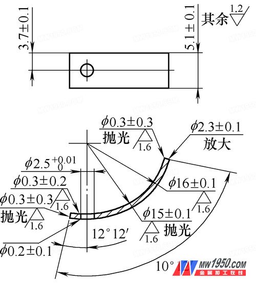
The parts are made of custom materials, each batch of materials is good or bad, the state and consistency are unstable, which is a factor to be considered in the processing. According to the needs of use and processing requirements, the pattern has changed several times, and now it is in the state shown in Figure 1.
First, process planning
1. Part structure size characteristics and requirements
(1) Part structure and size requirements The parts are nickel-copper alloy rods with specifications of φ45mm, no surface treatment and heat treatment requirements. The structural dimensions are shown in Figure 1.

figure 1
The part 1/4 is annular, the inner arc size is R15 mm±0.1mm, the surface roughness value Ra=1.6 μ m, polishing is required; the outer arc R16 mm±0.1 mm, the surface roughness value Ra=1.6 μ m A centripetal hole on the arc surface is φ2.5+0.02 0 mm, and the rounded corner is rounded with R=0.3mm at the inner arc interface, and the chamfer is C0.2 mm at the interface with the outer arc; the positioning dimension of φ2.5 mm is (3.7±0.1)mm, angular dimension 12°±2°; Remarks When processing is required, the material with a core diameter of φ15mm should be removed and cannot be used for part processing.
2. Mechanical processing technology analysis
(1) Parts analysis According to the design requirements of the parts, the design and processing of the process should be considered: 1 The nickel-copper alloy used for the parts is only φ45mm bar, the initial hardness HRC≥38, which is not conducive to cutting. 2 Design requirements The core part of the material φ15mm can not be used for part processing, and special measures need to be guaranteed. 3 The structure of the part is simple, the shape is the structure of the revolving body, and the maximum material utilization rate on the restricted material should be analyzed and calculated in detail. 4 The shape of the part is a rotating body structure with a thickness of 0.8 to 1.2 mm. When machining a hole of φ2.5 mm on the arc surface, the clamping is difficult, and the angular dimension of the positioning hole is not easy to measure . 5 parts R15mm ± 0.1mm on the arc surface are required to be polished everywhere, arc surface polishing requires auxiliary means.
(2) Solution For the above analysis, combined with the existing production resources and processing methods, the solution is: 1 the material hardness is too high, the appropriate tool is used when processing the part, the material is conductive, and the method that does not require hardness can be used. Such as wire cutting, electric sparks, etc. 2 The machining of the centripetal hole φ2.50+0.02mm on the arc surface can be selected from the general milling, number milling and fitter machining methods. The shape of the part is a rotary body structure. All three methods require tooling; the hole machining requires angular positioning. The efficiency of general milling is very low; the digital milling method is frequently replaced, which does not reflect the advantages of high efficiency; with the production of a reliable tooling, the fitter becomes the optimal processing method. 3The polishing process parts have no strict precision and size requirements. With the existing processing methods, there are two methods: the manual sandpaper polishing by the fitter; the appropriate abrasives and parts are placed together in a closable container in a certain proportion, so that the parts and abrasives are produced. Relative motion achieves polishing.
Second, tooling design and use
Tooling design
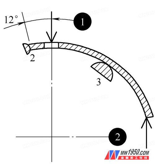
(1) Positioning analysis and tooling requirements As shown in Fig. 1, the centripetal hole φ2.50+0.02mm has a high precision, and the fitter's one-time drilling cannot guarantee the accuracy requirement, and a reaming is required.
When machining parts, the choice of positioning reference directly affects the positioning accuracy, affecting the processing efficiency and part qualification rate. According to the positioning reference selection principle, the positioning reference should be as close as possible to the design basis to reduce or eliminate the positioning reference error, thereby reducing the positioning error. There are two options for machining positioning of φ2.5+0.02 0mm holes. The analysis is as follows:

solar street light
solar flood light
highbay light
grow light
Modular Led Street Light,Outdoor Led Street Light,Waterproof Modular Street Lights,Modular Street Lights
zhongshanshi huadengxing lighting co., ltd , https://www.ledhdx.com