Abstract : This paper introduces the new technology and equipment used in the crankshaft production line of passenger car engines. It provides reference for the engine company's investment planning in the crankshaft production line, provides reference for the crankshaft processing project management personnel, and has certain support for improving the engine crankshaft manufacturing level in China. Guiding significance.
A crankshaft production line invested by Shenlong Company in recent years has only 17 processes and 19 sets of equipment. It is a U-shaped line layout with an area of ​​only 1 400m2 and a cycle time of 1.3min. It is equipped with 6 robots and only 8 operators. The annual output is 1.6. T/1.8T two kinds of turbocharged engine crankshafts of 200,000, its remarkable feature is the use of new crankshaft processing technology in recent years, such as quality center hole, high-speed external milling, the use of CNC crankshaft grinder, etc., simplifying the process , stabilize the processing process and improve the processing quality. Through the extensive use of CNC control technology and robots, an automatic production line has been formed, which has reduced the number of operators, shortened the processing time of single-piece products, and improved production efficiency.
1. Crankshaft machining process
Typical process flow for crankshaft machining of passenger car turbocharged engine: dynamic balance, center hole punching → car 5th spindle neck → car flange → roughing spindle neck, connecting rod neck and shoulder shoulder → drilling oil passage hole and pouring Angle → rough grinding spindle neck, connecting rod neck journal, side wall and undercutting groove → cleaning, drying, rounding rolling → finishing car, rolling stop surface + finishing small end → fine car flange end face and Groove→finish the main journal, connecting rod neck, small end→machined threaded hole at both ends, pin hole and hinge flange end center hole→finishing crankshaft flange end→crankshaft dynamic balance de-weight→sand belt polishing spindle neck The connecting rod neck and the outer neck of the flange → automatic inspection, marking → final cleaning of the crankshaft.
2. Application of advanced technology
(1) Dynamic balance and quality center hole. The positioning reference in the process of crankshaft machining is the center hole. According to its machining position, it can be divided into geometric center hole and mass center hole. The geometric center of the main bearing journal of the crankshaft can be found by V-shaped block or other means, and the center is machined out. The central hole is called the geometric center hole. The center of mass of the crankshaft is measured using dedicated test equipment, and the central hole machined in this center is called the center hole of the mass. When the geometric center hole is used for subsequent car and grinding, the workpiece rotates to generate centrifugal force, which will affect the processing quality, and the remaining dynamic unbalance after machining is large. In the dynamic balancing process, it is necessary to repeatedly measure and de-weight to achieve Technical requirements, low efficiency, affecting the production cycle, resulting in increased scrap rate of semi-finished products and loss of positioning components. Using the center hole of the quality can solve such problems and improve the cycle beat.
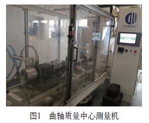
Figure 1 shows the COMAU SYMES10 crankshaft mass center measuring machine. The crankshaft is placed in the squirrel cage of the equipment and rotated together with the squirrel cage. The unbalance of the squirrel cage and the part is measured as M, and the unbalanced amount of the squirrel cage (M1) It is known that the unbalance amount of the part is M2 = M - M1. Through the special calculation formula, the equipment can automatically calculate the coordinate position of the balance shaft of the crankshaft through M2, and transmit the measurement result to the machining center of COMAUSDC700L automatic crankshaft. The measurement uncertainty is ≤40μm, and the crankshaft of multiple varieties can be measured. The parts can be automatically identified, the cycle time is 1.2min, and the equipment is simple and reliable.

(2) High-speed external milling rough machining crankshaft. High-speed external milling rough machining crankshaft main journal, connecting rod neck and shoulder, which is more efficient and stable than CNC turning, CNC internal milling and car-car pulling. For example, the CNC car-car pull process requires two steps of the connecting rod journal, and the CNC high-speed outer milling can be completed in one process. The remarkable features of the high-speed outer milling rough machining crankshaft are: cutting speed up to 350m/min, cutting time Short, short cycle time, low cutting force, low workpiece temperature rise, high tool life, fewer tool changes, higher machining accuracy and better flexibility are the development direction of crankshaft main journal and connecting rod journal roughing.
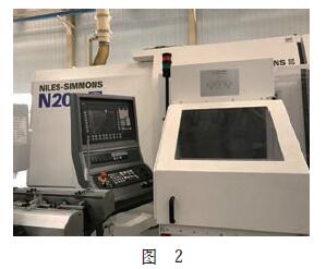
The NILES-SIMMONS N20 crankshaft external milling machine (see Figure 2) can machine the crankshaft main journal and the connecting rod neck at the same time. The machine tool adopts a double-pole spindle. The movement of each spindle is independent. Each spindle has a cutterhead, and each cutterhead is processed. The program and its parameters are independent. Place the part on the auxiliary feeding device, the auxiliary feeding device places the part into the processing area; the chuck clamps the part flange, the top is tightly pressed from the rear; the part rotates, and the left and right cutter heads are fixed on the tool spindle The speed is rotated while moving back and forth in the radial direction to realize the machining of the main journal and the connecting rod neck. Bed type (W/Z axis) linear rolling guide, horizontal carriage (U/X axis) linear rolling guide. The CNC control system uses the technical data of SINUMERIK 840D sl, the milling operation of the modular microprocessor CNC continuous track control, integrated PLC and digital complete solution SINAMICS S120.

(3) Application of CNC crankshaft grinding machine. Rough grinding of the main journal, connecting rod neck journal, side walls and undercutting grooves. CNC crankshaft grinding machine can grind all crankshaft main journal and connecting rod journal at one time. This kind of grinding machine is generally equipped with double grinding wheel head frame, which can meet multi-variety, low cost, high precision and mass production, application workpiece rotation and grinding wheel For servo linkage control technology, all journals can be ground without clamping the center of the crankshaft, including follow-up grinding of the connecting rod journal; static hydrostatic spindle, hydrostatic guide, static pressure feed Screw (sand head frame) and linear grating closed-loop control system, the grinding journal has high roundness precision and high grinding efficiency.
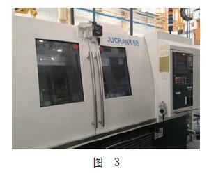
The JUCRANK 6S 10-10 CNC Cylindrical Crankshaft Grinder (see Figure 3) is used to roughen the main journal and connecting rod neck and undercut of the crankshaft. The robot that the device comes with picks up the part from the loading raceway and then places it on the pre-support block inside the equipment; the clamp automatically clamps the part; the part rotates, the two grinding wheels advance, and the radial movement according to the program, while grinding After the spindle neck and the connecting rod neck are finished, the grinding wheel is retracted. After the part stops rotating, the clamp is released, and the robot grabs the part and places it on the blanking raceway. The X/Z axis positioning accuracy is 0.004mm; the repeat positioning accuracy is 0.002mm; the MARPOSS automatic diameter gauge and the axis vector instrument are used to ensure the accuracy monitoring of the diameter and axial dimensions.

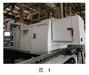
Finely grind the main journal, the connecting rod neck and the small end. Use the JUCENTER 6L CRANK CNC external crankshaft grinder (see Figure 4) to refine the main and neck of the crankshaft with two stations, the first station refining the crankshaft of the crankshaft and the second work The spindle neck of the refining crankshaft, the robot that comes with the equipment grabs the part from the loading raceway, and then places it on the pre-support block of the first station inside the equipment. The fixture of the first station automatically clamps the parts. The part rotates, the grinding wheel corresponding to the first station advances, and moves radially according to the program to grind the connecting rod neck; after the machining is finished, the grinding wheel retreats, and after the part stops rotating, the clamp is released. The robot grabs the part and places it on the pre-support block of the second station; the clamp of the second station automatically clamps the part, the part rotates, the grinding wheel corresponding to the second station advances, and the radial movement according to the program, grinding Spindle neck; after machining, the grinding wheel retreats, and after the part stops rotating, the clamp is released. The robot grabs the part and places it on the blanking track to start the next machining cycle. The X/Z axis positioning accuracy is 0.004mm; the repeat positioning accuracy is 0.002mm.

(4) Wide application of CNC horizontal lathes. The DANOBAT NA750 crankshaft thrust surface finishing machine is equipped with an automatic detection device. After the parts are clamped, the probe automatically detects the width of the thrust surface and determines its center line, which is used as the machining reference and according to the machining condition of the previous crankshaft. The automatic compensation is carried out, and the center line is used as the machining reference, and the two sides of the thrust surface are finished by the same amount. After the turning is completed, the width of the thrust surface is automatically detected, and the small end and the groove are processed at the same time. After the turning is completed, the turning tool is retracted, the rolling head is extended, and both ends are rolled. The rolling surface has good lubrication when rolling. The NA500 type precision flange end face and groove machine is equipped with automatic detection device. After the parts are clamped, the probe automatically detects the distance from the thrust surface to the flange end face. The X-axis positioning accuracy is 0.022 mm, the repeat positioning accuracy is 0.006 mm, the Z-axis positioning accuracy is 0.008 mm, and the repeat positioning accuracy is 0.004 mm.
(5) Application of crankshaft belt polishing machine. The oil seal neck, main journal neck and connecting rod neck of the crankshaft are polished by GRINDMASTER crankshaft belt polishing machine. The workpiece is sprayed and cleaned before polishing, and the parts are polished by sanding the parts. There are two directions of rotation during polishing. The final polishing direction is the same as the normal running direction of the engine (from the side of the flywheel). After polishing, the machine is equipped with a polishing liquid treatment system.
(6) Crankshaft fillet rolling machine. About HEGENSCHEIDT MFD7895 crankshaft rolling machine, its control system uses Siemens PLC S7-300, the machine is equipped with 9 rolling units, these units are used to roll and straighten the crankshaft, the maximum rolling pressure 30kN; pulse type Rolling the connecting rod neck to reduce the deformation of the workpiece; detecting and monitoring the rolling pressure by the pressure sensor and the position sensor and the rolling depth sensor integrated in the rolling unit; automatically detecting the spindle neck bouncing after rolling and rolling Straightening; equipped with a broken knife detection device; the electronic measuring probe performs radial runout measurement on all the main journals of the crankshaft; the highest point of the connecting rod neck is detected by the laser head to identify the type of the part.
(7) Crankshaft oil hole machining machine. HORKOS Imql crankshaft oil passage hole and chamfering machine tool, using 3 steps to machine the oil passage hole, milling plane → drilling oil passage hole → chamfering, overcoming the unstable quality of the drilling step of the original equipment, broken knife Frequent and manual chamfering, equipment and process capability values ​​are qualified once, and the cycle time is less than 1.3min.
(8) Crankshaft dynamic balance de-duty machine. COMAU SYME S10 measuring and correcting the crankshaft dynamic balancing machine consists of measuring station, pneumatic rotary transmission device and drilling correction station; balancing measurement, measuring and displaying unbalanced quantity, automatically decomposing and calculating drilling data, drilling correction, unbalanced recovery All actions such as checking are automatic. The measurement uncertainty of the measuring station is ≤1g·cm, and the maximum drilling feed rate of the calibration station is ≥500mm/min.
3. Conclusion
As the passenger car engine tends to be lighter, simpler in structure, and more efficient in performance, the manufacturing process of the crankshaft, which is the core component of the engine, will also undergo major changes. The high-speed, high-efficiency, flexible, and composite technology is the crankshaft manufacturing. The main direction of development, advanced crankshaft production line must be an automated production line with short production line, high efficiency, few personnel, stable production process and reliable product quality.
Industrial, Comercial And Agricultural Lighting
Industrial, commercial, and agricultural lighting refers to lighting systems used in industrial, commercial, and agricultural fields. These areas have different lighting needs, and the following are their characteristics and applications:
Industrial Lighting:
Industrial lighting is often used in industrial environments such as factories, warehouses, and production lines. These places usually require high brightness, uniform, and long-lasting lighting. LED high-brightness lamps are widely used in industrial lighting, and they have the advantages of long life, high energy efficiency, and low maintenance costs. In work areas with special requirements, such as cleaning rooms and explosion risk areas, special harsh lighting lamps that meet the relevant standards need to be selected.
Commercial Lighting:
Commercial lighting is used in commercial buildings such as malls, retail stores, and office Spaces. Commercial lighting requires the provision of good lighting effects to display products and create a comfortable shopping environment. LED lamps are widely used in commercial lighting because they can offer a variety of color and dimming options to meet different scenarios and needs.
Agricultural Lighting:
Agricultural lighting is used in agricultural production environments such as indoor agriculture, greenhouses, and plant factories. Its purpose is to supplement or replace natural light and promote plant growth and development. LED plant growth lamps are commonly used farmhouse lighting solutions that can provide specific spectra to meet different plant growth stages and needs. Proper lighting design in indoor planting can improve crop yield, quality and control the growth cycle.
The above is a brief introduction to industrial, commercial and agricultural lighting. Each area of lighting needs has its specific considerations, and LED lamps are widely used in these areas due to their high energy efficiency, long life, and dimmable characteristics. Choosing the right lighting solution can increase efficiency, save energy and meet a variety of needs.
Industrial Lighting,Commercial Plaza Lighting,Farmhouse Lighting,Harsh Lighting,Agricultural Lighting
SHENZHEN LITEHOME OPTOELECTRONIC TECHNOLOGY CO., LTD. , https://www.litehomelights.com


